In one form or another, gearboxes have been around for a very long time. The first gearbox was invented back in 1904, over 115 years ago, and was called the 'horseless carriage’ gearbox. It was invented by the Sturtevant brothers who were based in Boston, Massachusetts, in the United States. While this was the first of many automatic gearboxes made, it wasn't mass-produced and was only available for a select few. The masses would have to wait 35 years, a world war, and an economic collapse, until they could enjoy the benefits of affordable gearboxes, when, in 1939, General Motors released the Hydramatic three-speed automatic gearbox, by which time Highfield Gears had already been around for 12 years!
Since that invention back in the early 20th century, gearboxes have gotten bigger, more efficient, and able to power a host of different applications from the car, right the way through to industrial equipment that helps brew beer, make steel, and mass-produce products. And, while most people may be able to point to a gearbox and recognise it, not many would know how it works. Of course, here at Highfield Gears, the inner workings of industrial gearboxes is our life. There’s not a day that goes by where we don’t think about couplings, seals, grinding, boring, and bevels, but for the average industrial gearbox owner they may not be aware of the science that goes into ensuring their machinery works smoothly. Here, we’re going to be looking at how a gearbox works in a little more detail so that you’ll be able to spot issues, understand what to look for, and maybe fix small problems yourself.
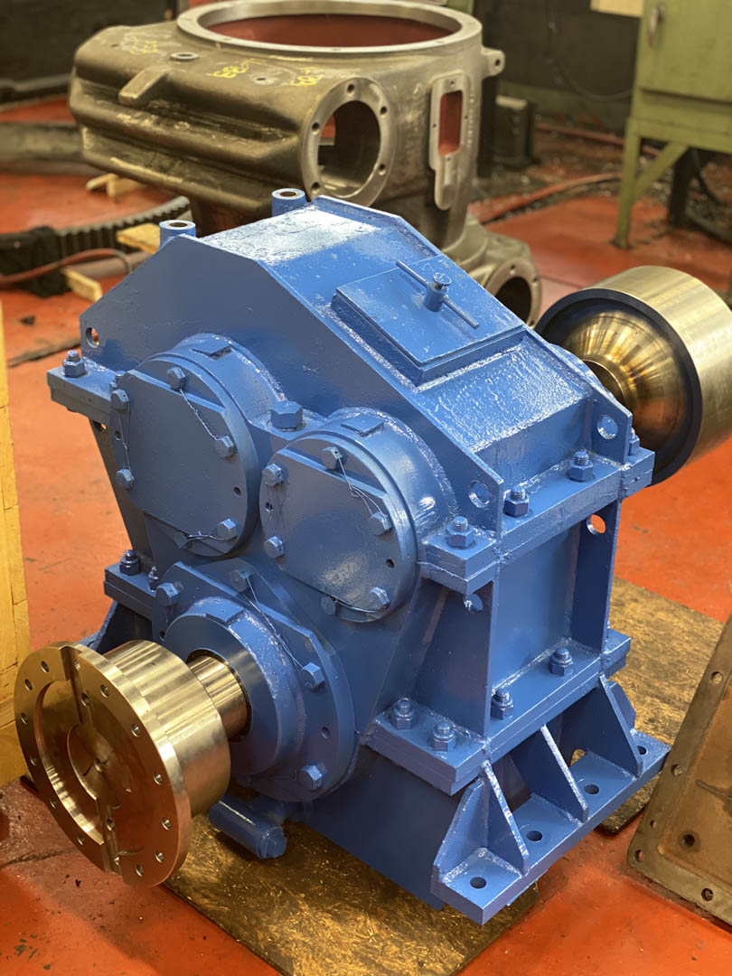
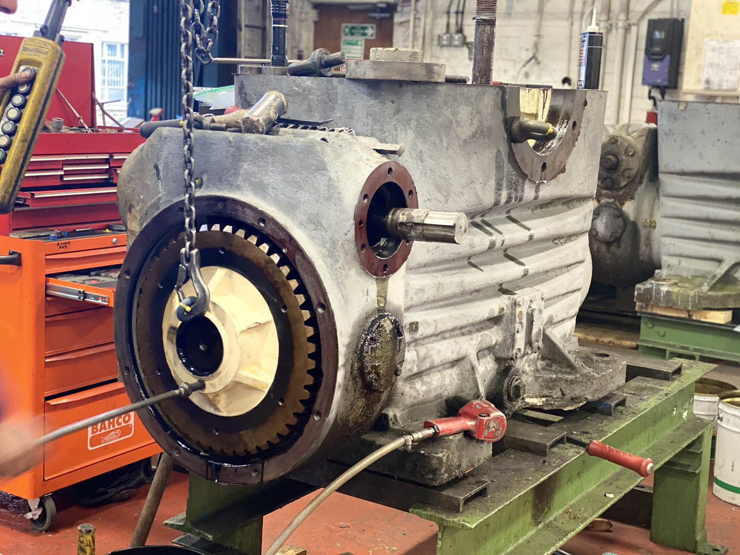
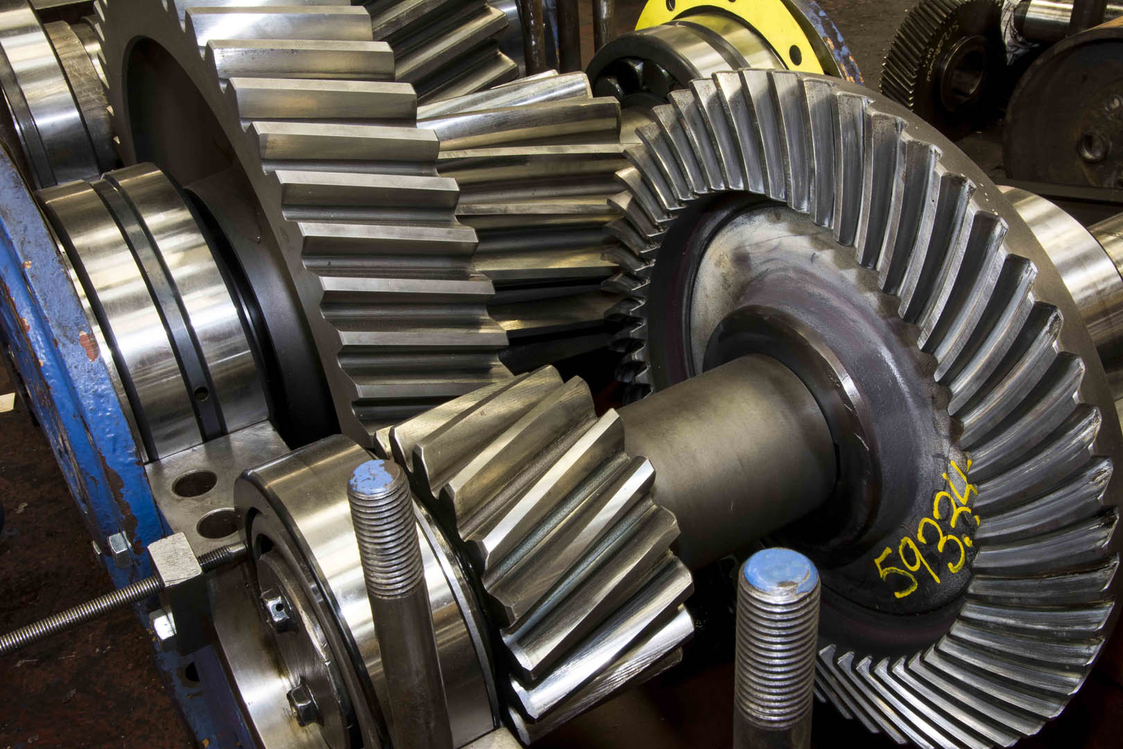
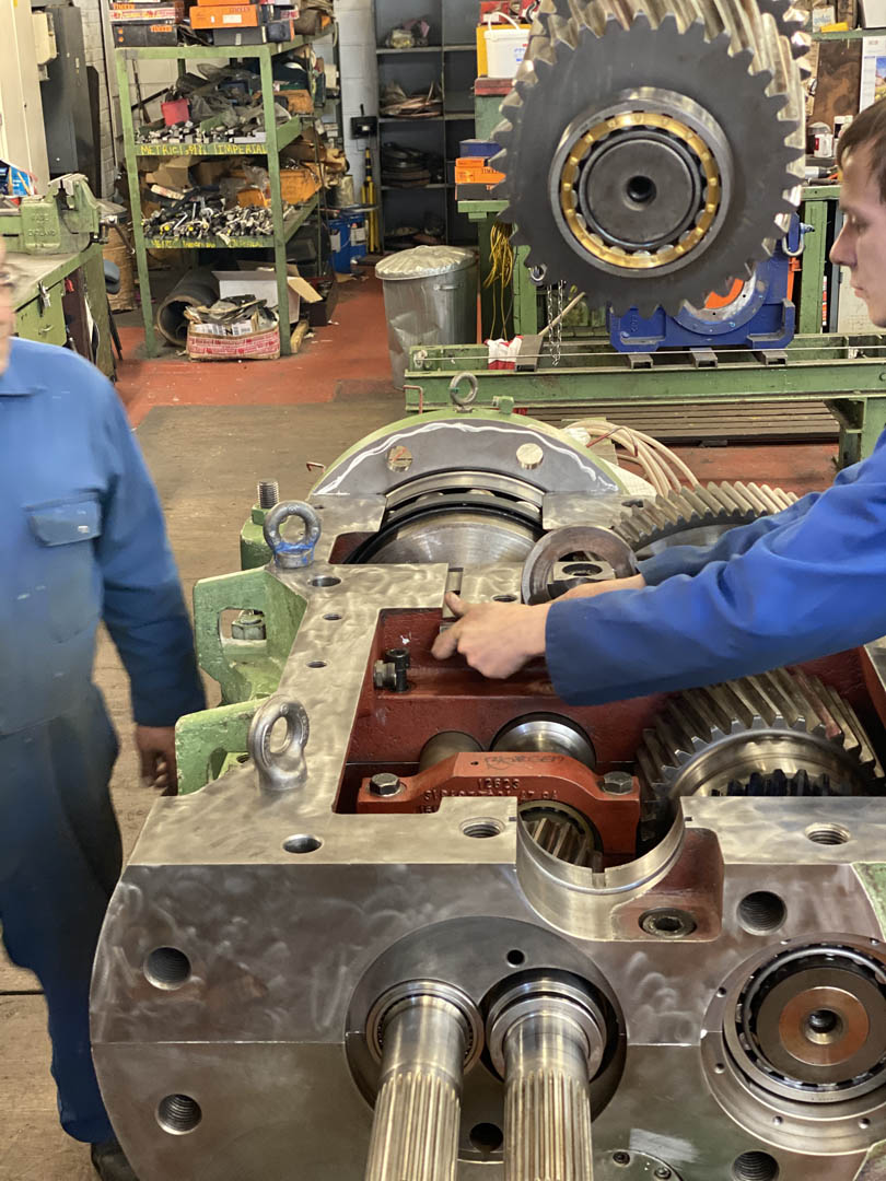
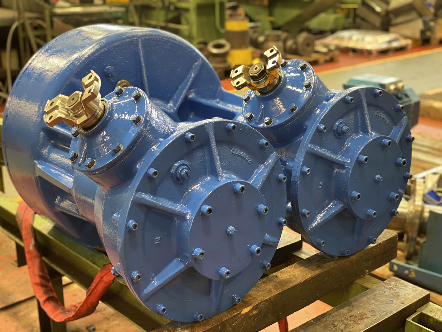
A gearbox is a unit that is made up of mechanical components, most notably, gears. These gear rotate within the casing and can be designed in various ways, depending on the intended application. The gears can interact to, for example, increase or decrease speeds, change the direction of an application, or alter the levels of torque. The gearbox works by transferring energy between gears so that the application (e.g. machinery) that it is powering enacts the process that it is designed for. Gearboxes and their components form part of the wider transmission system which is responsible for making the machine work, and ‘go’.
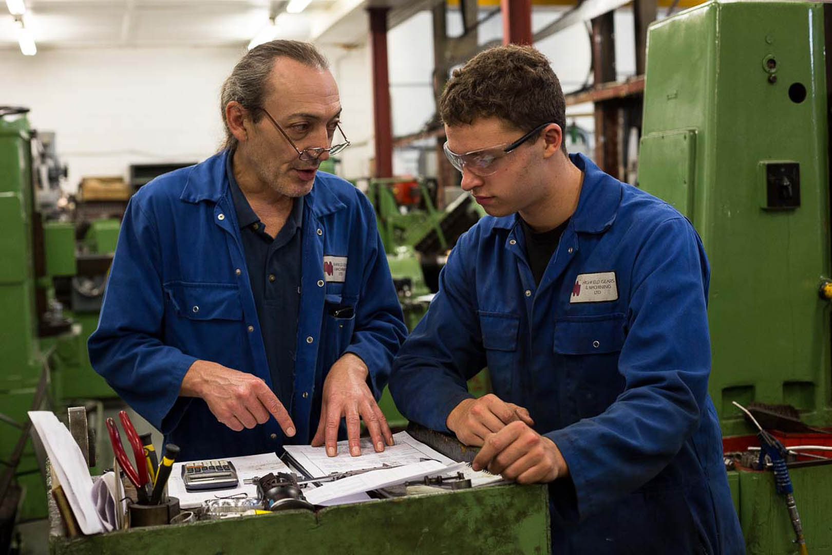
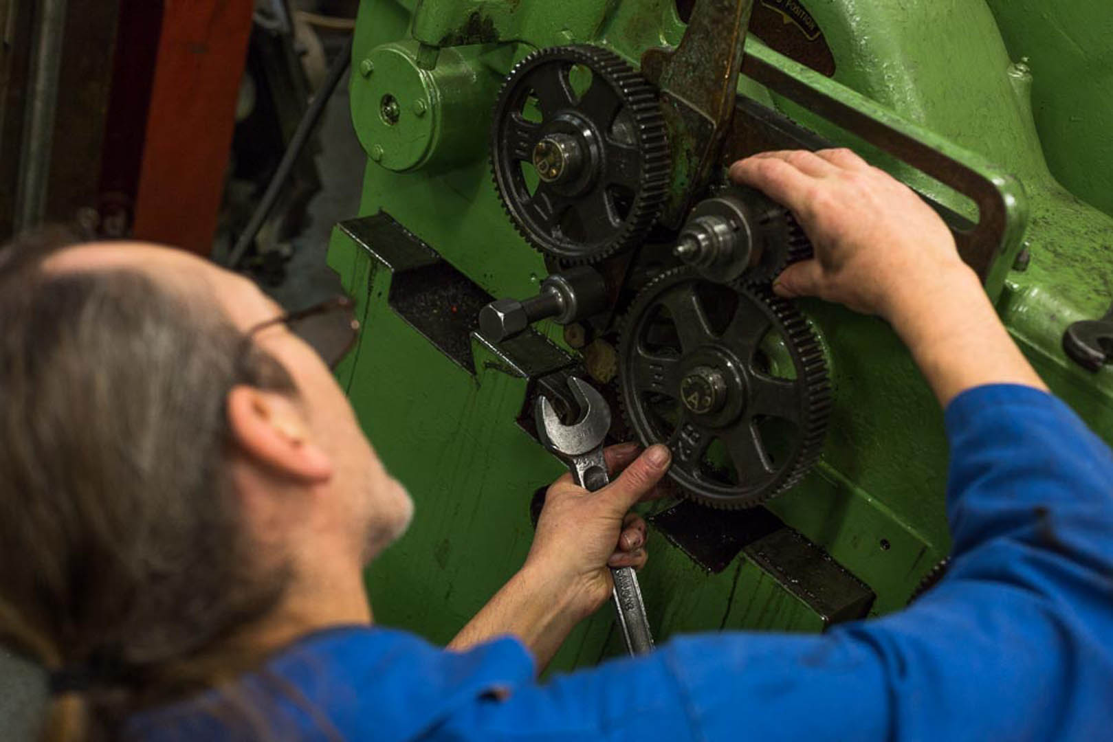
In industrial gearboxes, the different couplings, gears, and shafts all work together to affect the speed and process of the application. These components must be synced, well-made, and constantly monitored to ensure they are all doing their part, and are all working together so that power flows smoothly between components. If any of these things aren’t in sync it can cause disruption and put pressure on other areas of the process which will, very quickly, result in faults and potential breakdowns. Similarly, if industrial gearboxes aren’t monitored regularly then small issues could manifest into something greater, resulting in a replacement gearbox. It’s important when understanding how a gearbox works, to set performance benchmarks and have clear expectations of how your transmission units should perform. By doing this, you’ll be able to spot problems quicker because you’ll have an idea of how your transmission systems work during ‘normal’ times.
That aside, all gearboxes work in broadly the same way, the rotational direction of the gears will depend on the direction of input and the gear orientation. They are used to maintain the direction of rotation, while also converting either torque or power between the respective inputs to help the applications reach the necessary speed to carry out their task. Clearly, their uses are multiple and you’ll find industrial gearboxes in machining tools, construction machinery, power transporters, or anything that requires a change in speed, direction, or torque.
What you’ll find ‘under the hood’ of a gearbox will vary depending on the type of unit you have. Most are almost always made of some sort of metal such as iron, aluminium, or a brass-like material, and some units can be made using polycarbonates or plastics. The choice of material will need to be carefully considered as the wrong material can cause overheating, and excess wear and tear.
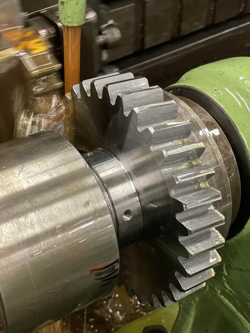
The gear teeth are also a common component of the unit and, like the material selected, the type of teeth will greatly alter the performance. Regular gear teeth will be used for slower applications whereas helical gears (those that are curved or positioned at an angle) will be used for higher speed applications that need to quickly, and smoothly, transfer power.
